If you need to assemble and connect an electrical panel in a private home, but there is no desire or opportunity to seek the help of an electrical installation specialist, we will tell you how to do it correctly.
Doing all the work with your own hands is not easy, and even dangerous if you do not follow the rules for working with electricity. We will try to clarify all questions for you and point out pitfalls.
The design implies the presence of mechanisms to protect people and wiring from overload or short circuit, as well as a counter. The cable goes from the power line to the house to the electrical panel and all the electrical groups of the house are routed from it.
In fact, the correct name for this device is input distribution device(VRU). But according to the law, you must divide this unit into two and one of them will be input, and the second distribution.
The input device is usually installed on an electrical pole and is an electrical panel, in which a window has been made for the convenience of taking readings. Inside there is a general input, arresters (they are rarely installed), and elements for overvoltage protection. This design should be installed at a height of no more than 2 meters.
From the input panel it is led to the distribution installation. In private homes this means use of devices and residual current devices. To save space in the switchboard, differential devices are installed, which include a circuit breaker and.
The material from which the house is made, as well as where the shield itself is located, determines which of its options will be chosen.Metal mounted electrical panels are used in wooden houses, and in stone houses, where it is drier, you can install a plastic box or a built-in panel.
The place for installing one single-phase circuit breaker is called a module. Each shield has a different number of modules, so you need to know what and how many devices will be in the panel.
The distribution block should be installed in a safe place, preferably in a separate nook.Preparing to install the distribution board
Must be done before assembly:
- Select the electrical panel according to the type.
- Calculate the total power load of each group.
- Calculate the load on each group based on the power of each device.
- Think about the places where work is required.
Full list of equipment:
- Single-tariff electric meter with accuracy class from 2.
- Input machine 32 A.
- Two-pole 16 A, 2 pieces.
- Single-pole backup, 2 pieces.
When buying an electrical panel, do not skimp, since a cheap shield will most likely have to be redone and re-equipped, and poor plastic will become brittle over time. In addition, in the event of a fire, inexpensive shields do not comply with all safety measures.
Electrical panel connection diagrams for 220V and 380V
For clarity, you should create a diagram according to which the shield will be assembled.
An example of a wiring diagram for an incoming electrical panel in a private house for 220V:

In private homes, electrical wiring is often installed 380V distribution boards, a 4- or 5-core cable is supplied to such a shield: two or three phases, neutral and ground.
The assembly diagram for a 380 V electrical distribution panel for a private house will be as follows:

Diagram of how to properly install an electrical panel in a wooden private house:

Installation of a shield for a suburban building
- We install the Din rails onto which all the equipment will be attached using self-tapping screws. They must have size 35 mm.
- We proceed to install the equipment according to pre-made diagram and calculations, we install automatic devices, RCDs and two separate buses, to which the zero is connected, and install a metering device.
- We connect the phase wires, using a special bus we connect the machines. According to the general rules for connecting such devices, the input should be at the top and the output at the bottom.
- We install protective covers and sign all machines for convenience.
- Then we connect them with a special comb or make jumpers from wire. If you are going to use a comb, remember that the cross-section of its core must be at least 10 mm/sq..
- We feed them into machines from consumers.
Find out from this video how to properly assemble a 220 V electrical panel in a private house:
From the following video you will learn how to make a three-phase 380 V electrical panel in a private house:
After you have assembled the shield without closing it, turn it on for a few hours and then check the temperature of all elements.
Do not allow the insulation to melt, otherwise a short circuit will occur in the future.
With a careful, consistent approach and Following electrical safety rules, anyone can assemble an ASU independently, although you will have to tinker. Having completed the installation, all you have to do is wait for representatives of the electrical network company, who will check your circuit and arrange the connection.
Connecting circuit breakers in a distribution board requires a lot of knowledge. First, you need to correctly design the electrical wiring, then choose a location, make diagrams, select a housing and components. After all these procedures, you need to install the equipment and connect the shield to the cable.
Incorrectly connecting the machines can lead to big problems with the wiring, so in this case it is better to contact an experienced electrician.
In this article we will talk about the process of correctly connecting machines to the panel, laying cables and the correct arrangement of all parts. It is impossible to imagine a modern house without electricity; this issue should be one of the first places.
Electrical panel for the meter and machines - choosing an installation location
Let's start with the simplest part - where to place the switchboard in the apartment? It is most convenient to place it near the front door in the hallway. In this case, you will not have to pull the power cable far from the site. The most optimal height option is at the eye level of an adult. And it’s convenient to take meter readings and turn off the machines if necessary.
For those who support pushing everything under the ceiling, “for greater security, like they used to hang meters,” let’s say the following. Old electric meters with plug fuses were simply mounted on the wall without boxes, and therefore were hung from the ceiling.
A modern electrical panel has a durable casing and is locked, so children will not get in unless you leave the key in a visible place.
When choosing a location for installing a panel in a private house or cottage, you need to consider where and how the cable from the overhead line or underground supply line is or will be installed. Data on external networks can be obtained from local energy sales.
Buy a ready-made one or assemble an electrical panel yourself
As they say in the old song “what progress has come”, you can buy a ready-made shield with a full filling or assemble a ready-made one. If your electrician suggests such a “proprietary” assembly design, then do not be alarmed. The panels are assembled by enterprises and electrical installation companies, including on order or for standard residential wiring projects.
The main point that needs to be clarified is whether your master has worked with ready-made shields before or this is his first experience. If he has installed a dozen or two such assemblies and knows their features, then feel free to agree. But if you are a “guinea pig” for the first experiment, refuse. It’s better to let him assemble it himself, with his own hands, the old fashioned way.
Connection diagram for machines in the panel
The layout of the panel in the apartment is one of the main points, but before we deal with it, let's see what elements are included in the design. So that you can understand the symbols and composition of the wiring diagram.

- Typically, when installing a shield, use:
- Introductory machine.
It is placed to protect the entire wiring circuit. The cores of the main incoming cable are connected to the terminals of the input circuit breaker. For convenient work with the electrical panel, a switch is often installed in front of the input circuit breaker.
It allows you to de-energize the entire assembly to replace elements, safe preventative maintenance, and completely shuts off the power supply to your apartment or house. In this case, the power cable is connected to the switch.
- Electric meter.
It is installed after the introductory machine and calculates the energy consumption in a house or apartment. Sometimes the meter stands separately, up to the panel, along with a circuit breaker. For example, on the site of an apartment building.
- Residual current device - designed to protect against electric shock and prevent fires.
The RCD in the circuit can be one, installed after the meter, for example, in a one-room apartment with a small load. Or they install several RCDs on separate lines with high consumption (for an electric stove, washing machine, air conditioner).
- Linear machines.
Needed for separate lines for different rooms, household appliances and lighting. They break the circuit if an overcurrent or short circuit is detected, protecting the wiring and connected equipment from damage. Triggering the machine can prevent a fire due to heating and ignition of the wire.
- Diffautomatic protection.
It can be installed instead of a pair of automatic circuit breaker + RCD on separate power lines of electrical appliances.
- DIN rail is a mounting element for installing equipment.
Attached to the rear wall of the electrical panel housing. Depending on the dimensions of the cabinet, the number of DIN rails and the possible number of installed modules may vary. In order not to make a mistake when purchasing a switchboard housing based on the number of modules, you need to draw up a wiring diagram.
- Connecting busbars.
Needed for disconnecting the electrical panel and connecting working zeros and grounding wires. The panel uses both neutral terminal bars and grounding ones.
- Distribution buses.
Installed for a “bundle” of linear machines, RCDs, and automatic circuit breakers. Comb busbars have reliable insulation and allow you to quickly and safely connect a number of machines through the input terminal block. They can be used both for the current conductor and for the working zero.
What are circuit breakers
These are specially designed devices whose main task is to protect wiring from melting. In general, automatic machines will not save you from electric shock and will not protect your equipment. They are designed to prevent overheating.
- The method of their operation is based on opening the electrical circuit in several cases:
- short circuit;
- exceeding the current flowing through a conductor not intended for this purpose.
As a rule, the machine is installed at the input, that is, it protects the section of the circuit that follows it. Since different wiring is used for wiring different types of devices, this means that protection devices must be able to operate at different currents.
At first glance, it may seem that it is enough to simply install the most powerful machine and there will be no problems. However, it is not. A high current, for which the protection device does not respond, can overheat the wiring and, as a result, cause a fire.
What does the machine consist of?
- A typical machine consists of the following elements:
- Cocking handle. Using it, you can turn on the machine after it has been triggered or turn it off to de-energize the circuit.
- Switching mechanism.
- Contacts. Provide connection and breaking of the circuit.
- Terminals. Connect to a protected network.
- A condition-triggered mechanism. For example, a bimetallic thermal plate. Many models may have an adjusting screw to adjust the nominal current value.
- Arc extinguishing mechanism. Present at each pole of the device. It is a small chamber in which copper-plated plates are placed. On them the arc is extinguished and comes to naught.

Depending on the manufacturer, model and purpose, machines can be equipped with additional mechanisms and devices.
Shutdown mechanism design
The machines have an element that breaks the electrical circuit at critical current values.
- Their operating principle can be based on different technologies:
- Electromagnetic devices. They are characterized by a high speed of response to a short circuit. When currents of unacceptable magnitude are applied, the coil with the core is activated, which, in turn, turns off the circuit.
- Thermal. The main element of such a mechanism is a bimetallic plate, which begins to deform under the load of high currents. By bending, it has a physical effect on the element that breaks the chain.
An electric kettle works in approximately the same way, which can turn itself off when the water in it boils. There are also semiconductor circuit breaking systems. But they are used extremely rarely in household networks.
Time-current characteristics of circuit breakers
The devices differ in the nature of their response to an excessively high current value. There are 3 most popular types of slot machines - B, C, D.
- Each letter means the sensitivity coefficient of the device:
- B (from 3 to 5 xln);
- C (from 5 to 10 xln);
- D (from 10 to 20 xln).
What does it mean? It’s very simple - to understand the range at which the machine is capable of operating, you need to multiply the number next to the letter by the xln value.
- So for the B16 machine gun:
- 16*3=48A;
- 16*5=80A.
- Let’s take, for example, three machines with the same rated current of 16A, but different time-current characteristics:
- the machine marked B16 will turn off in the range 48...80A;
- marked C16 will turn off in the range 80...160A;
- and marked D16 will turn off in the range 160...320A.
The most common type of machine is C, it is used in almost every home.
Machines marked D are used mainly in places with consumers that have large starting currents, for example, electric motors.
Type B is the most sensitive and is rarely used, mainly to protect electronic equipment. And it costs correspondingly more.
At a current of 100 A, the B16 circuit breaker will turn off almost instantly, while the C16 will not turn off immediately, but after a few seconds from thermal protection (after its bimetallic plate heats up).
Legend
Different types of machines are marked in their own way for quick identification and selection of the one needed for a specific circuit or its section. As a rule, all manufacturers adhere to one mechanism, which allows them to unify products for many industries and regions.
- Let’s take a closer look at the signs and numbers printed on the machine:
- Brand. Usually the manufacturer's logo is placed at the top of the machine. Almost all of them are stylized in a certain way and have their own corporate color, so choosing a product from your favorite company will not be difficult.
- Indicator window. Shows the current status of contacts. If a malfunction occurs in the machine, then it can be used to determine whether there is voltage in the network.
- Machine type. As already described above, it means a shutdown characteristic at currents significantly exceeding the rated current. C is used more often in everyday life and B is used a little less frequently. The differences between the types of electric machines B and C are not so significant;
- Rated current. Shows the current value that can withstand a long-term load. Rated voltage. Very often this indicator has two meanings, written separated by a slash. The first is for a single-phase network, the second is for a three-phase network. As a rule, in Russia a voltage of 220 V is used.
- Switch-off current limit. It means the maximum permissible short circuit current at which the machine will turn off without failure. Current limiting class. Expressed in one digit or absent altogether
- Scheme. On the machine you can even find a diagram for connecting contacts with their designations. It is almost always located in the upper right part. Thus, by looking at the front of the machine, you can immediately determine what type of current it is intended for and what it is capable of.
Which type of machine to choose
When choosing a protective device, one of the main characteristics is the rated current. To do this, you need to determine what current strength is required by the totality of all consumer devices in the house.
And since electricity flows through wires, the current required for heating depends on its cross-section. The presence of poles also plays an important role.
- The most commonly used practice is:
- One pole. Circuits with lighting devices and sockets to which simple devices will be connected.
- Two poles. It is used to protect wiring connected to electric stoves, washing machines, heating appliances, and water heaters. It can also be installed as protection between the shield and the room.
- Three poles. Used primarily in three-phase circuits. This is relevant for industrial or near-industrial premises. Small workshops, production and the like.
The tactics for installing machine guns proceed from larger to smaller. That is, first it is mounted, for example, double-pole, then single-pole. Next come devices with power that decreases at each step.
The first thing to start with is whether the machine is connected correctly in principle. As you know, a circuit breaker has two contacts for connection, movable and fixed.
Which pin should be connected to the top or bottom? To date, there has been a lot of controversy regarding this matter. There are a lot of questions and opinions on this matter on any electrical engineering forum.
Let's turn to regulatory documents for advice. What does the PUE say about this? In 7th edition PUE clause 3.1.6. said:
3.1.6. Automatic switches and plug-type fuses must be connected to the network so that when the fuse plug (circuit breaker) is unscrewed, the screw sleeve of the fuse (circuit breaker) remains without voltage. With one-way power supply, connecting the supply conductor (cable or wire) to the protection device should be performed, as a rule, on fixed contacts.
As you can see, the rules say that when connecting machines in a panel, the supply wire should, as a rule, be connected to fixed contacts. This also applies to all RCDs, automatic circuit breakers and other protection devices. From this entire clipping, the expression “as a rule” is not clear. That is, it seems to be as it should be, but in some cases there may be an exception.
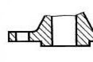
To understand where the moving and fixed contacts are located, you need to imagine the internal structure of the circuit breaker. Let's use the example of a single-pole circuit breaker to look at where the fixed contact is located.

Before us is an automatic machine of the BA47-29 series from iek. From the photo it is clear that its fixed contact is the upper terminal, and the moving contact is the lower terminal. If you look at the electrical symbols on the switch itself, you can also see that the fixed contact is on top.
Circuit breakers from other manufacturers have similar markings on the housing. Take, for example, the Schneider Electric Easy9 machine; its fixed contact is also located on top. For Schneider Electric RCDs, everything is similar on top there are fixed contacts and moving ones below.
Another example is safety devices from Hager. On the housing of the hager circuit breakers and RCDs you can also see symbols, from which it is clear that the fixed contacts are located on top.
Let's figure out from the technical side whether it matters how to connect the machine from above or below.
The circuit breaker protects the line from overloads and short circuits. When overcurrents occur, the thermal and electromagnetic releases located inside the housing react.
From which side the power will be connected from above or below to trigger the releases there is absolutely no difference. That is, we can say with confidence that the operation of the machine is not affected by which contact the power is supplied to.
In truth, I should note that manufacturers of modern “branded” modular devices, such as ABB, Hager and others, allow power to be connected to the lower terminals. For this purpose, the machines have special clamps designed for comb tires.
Why do the PUE recommend connecting to fixed contacts (top)? This rule was approved for general purposes. Any educated electrician knows that when performing work it is necessary to remove voltage from the equipment on which he will work.
“Climbing” into the electrical panel, a person intuitively assumes the presence of a phase on top of the machines. Having turned off the AV in the panel, he knows that there is no voltage at the lower terminals and everything that comes from them.
Now let’s imagine that the connection of the circuit breakers in the distribution board was carried out by an electrician, Uncle Vasya, who connected the phase to the lower AB contacts.
Some time has passed (a week, a month, a year) and you have a need to replace one of the machines (or add a new one). Electrician Uncle Petya comes, turns off the necessary machines and confidently reaches into the voltage with his bare hands.
In the recent Soviet past, all machine guns had a fixed contact at the top (for example, AP-50). Nowadays, based on the design of modular AVs, you can’t tell where the movable and where the fixed contact is. For the ABs that we discussed above, the fixed contact was located on top. Where are the guarantees that Chinese machines will have a fixed contact located on top?
Therefore, in the PUE rules, connecting the supply conductor to fixed contacts only means connecting to the upper terminals for the purposes of general order and aesthetics. I myself am a proponent of connecting power to the top contacts of the circuit breaker.
For those who do not agree with me, a quick question is why in the electrical diagrams the power supply to the machines is connected precisely to the fixed contacts.
If we take, for example, a regular switch of the RB type, which is installed at every industrial facility, then it will never be connected upside down. Connecting power to switching devices of this kind relies only on the upper contacts. I turned off the switch, and you know that the lower contacts are without voltage.
Connecting circuit breakers
Once the machine is selected, it must be connected. Connecting circuit breakers is not a difficult task and anyone can do it.
Automatic switches are installed in the box for electrical circuit breakers. To securely fix the machine in the electrical panel, it is mounted on a special DIN rail. The wires in the terminals of the machine are fixed using bolted contacts.
During installation in electrical panels and connecting supply or outgoing lines, it is necessary to tighten the bolted contacts carefully, without excessive force.
Tightening the contacts should not be accompanied by deformation of the machine body, as this can lead to a violation of the positions of current-carrying parts inside the machine body, which can cause excessive overheating of the machine and its failure even under light loads.
When connecting a machine, you must follow the generally accepted rule: the input (power) is connected on top of the machine, and the output (load) is connected on the bottom.
In the future, when there is a need to replace or connect additional wires to a working machine, you will always know which contact the load and power are connected to.
Before connecting the cable cores to the terminals of the machine, the outer insulation of about 10-15 cm is removed from it, after which the cable becomes more flexible and easily bends inside the electrical panel. This simplifies installation, especially if many machines are installed in the switchboard. Next, approximately 5-10mm of internal insulation is removed from the wires.
If you need to connect small-section wires or stranded wires to the machine, it is advisable to use special lugs.
Where are one-, two-, three- and four-pole circuit breakers used and how are they connected?
In single-phase networks with a voltage of 220 V, single-pole or double-pole circuit breakers are usually installed to protect electrical appliances.
- Only the phase wire - L - is connected to single-pole circuit breakers.
- Both wires are connected to two-pole wires, the phase wire is L and the neutral wire is N.
- Three-pole circuit breakers are used in 3-phase networks. Three phases of the power supply L1, L2, L3 are connected to the terminals of such machines.
- Four-pole circuit breakers are used in places stipulated by the rules of the PUE. As a rule, these are four-wire networks with a solidly grounded neutral, which uses three phases L1-L2-L3 and a zero working one - N (TN-S system).

Basic mistakes when connecting machines
- Let's look at the most common errors:
- connecting the ends of the cores of a flexible stranded wire without termination;
- insulation coming into contact;
- connecting wires of different sections to one terminal;
- soldering the ends of the cores.
The main mistake when connecting machines is the use of a flexible stranded wire without termination. It's easier and faster, but not correct. It is impossible to clamp such a wire reliably; over time, the contact weakens (“flows”), the resistance increases, and the junction heats up.

It is necessary to use lugs on a flexible wire or use a rigid single-core wire for installation.
Everyone knows that before connecting the machine in the panel, you need to remove the insulation from the connected wires. It would seem that there is nothing complicated here, I stripped the core to the required length, then we insert it into the clamping terminal of the machine and tighten it with a screw, thereby ensuring reliable contact.
But there are cases when people are perplexed why the machine burns out when everything is connected correctly. Or why the power in the apartment periodically disappears when the wiring and filling in the panel are completely new.
One of the reasons for the above is that the wire insulation gets under the contact clamp of the circuit breaker. Such a danger in the form of poor contact carries the threat of melting of the insulation, not only of the wire, but also of the machine itself, which can lead to a fire.

To exclude this, you need to monitor and check how the wire is tightened in the socket. Correct connection of circuit breakers in the distribution board should eliminate such errors.
Never connect machines with jumpers and cables of different sections. When tightening the contact, the core with a larger cross-section will clamp well, and the core with a smaller cross-section will have poor contact. As a result, the insulation melts not only on the wire, but also on the machine itself, which will undoubtedly lead to a fire.
- An example of connecting circuit breakers with jumpers from different cable sections:
- The first machine receives a “phase” with a 4 mm2 wire,
- and other machines already have jumpers with 2.5 mm2 wire.
As a result, poor contact, increased temperature, melting of insulation not only on the wires, but also on the machine itself.

For example, let's try to tighten two wires with a cross-section of 2.5 mm2 and 1.5 mm2 into the terminal of the circuit breaker. No matter how hard I tried to ensure reliable contact in this case, nothing worked. A wire with a cross-section of 1.5 mm2 dangled freely and sparked.

Separately, I would like to dwell on this method of terminating wires in a shield, such as soldering. Human nature is such that people try to save money on everything and do not always want to spend money on all kinds of tips, tools and all sorts of modern small things for installation.
For example, consider the case when an electrician from the housing office, Uncle Petya, wires the electrical panel with a multi-core wire (or connects outgoing lines to the apartment). He does not have NShVI tips. But you always have a good old soldering iron at hand.

And the electrician, Uncle Petya, finds no other way out than to tin the multi-wire core, pushes the whole thing into the contact clamp of the machine and tightens it with a screw. Why is it dangerous to connect circuit breakers in a distribution board?
When assembling distribution boards, DO NOT solder or service the stranded core. The fact is that a tinned connection begins to “float” over time. And for such contact to be reliable, it must be constantly checked and tightened. But as practice shows, this is always forgotten.
The soldering begins to overheat, the solder melts, the joint weakens even more and the contact begins to “burn out.” In general, such a connection can lead to a FIRE.
How to properly connect an electric meter and machines
- To ensure the safe operation of your shield, follow these simple rules:
- use single-wire monolithic wire for installation;
- when using flexible wire, use ferrules;
- use unbreakable jumpers;
- use a U-bend to increase the contact area.
Using lugs on flexible wire
For wiring panels, electricians often prefer a flexible wire with a stranded core of type PV-3 or PuGV. It is easier and easier to work with than with a monolithic core. But there is one peculiarity here.
The main mistake that beginners make in this regard is connecting a stranded wire to the machine without termination. If you clamp a bare stranded wire as it is, then when tightening the strands are squeezed and break off, and this leads to loss of cross-section and deterioration of contact, and the contact itself weakens over time.
Experienced “specialists” know that it is impossible to tighten a bare stranded wire into a terminal. Therefore, if a stranded wire is used during installation, then NShV or NShVI lugs must be used to terminate it.

In addition, if there is a need to connect two stranded wires to one terminal of the machine, for this you need to use a double tip NSHVI-2. Using it, it is very convenient to form jumpers for connecting several group circuit breakers.

Using a U-Bend
To connect the cores of outgoing wires and cables to the machines, we remove the insulation from them by about 1 cm, insert the bare part into the contact and tighten it with a screw. According to statistics, 80% of electricians make connections this way.
The contact at the junction is reliable, but it can be further improved without wasting time and money. When connecting cables with a monolithic core to circuit breakers, make a U-shaped bend at the ends.

This formation of the ends will increase the area of contact of the wire with the surface of the clamp, which means the contact will be better.
The inner walls of the AB contact pads have special notches. When the screw is tightened, these notches cut into the core, thereby increasing the reliability of the contact.
If there is a need to connect several machines standing in the same row from one source (wire), a comb bus is ideally suited for this purpose. But such tires are not always at hand.
How to combine several group machines in this case? Make a homemade jumper from cable cores. To do this, use pieces of wire of the same cross-section, or better yet, do not break it along its entire length.
- How to do it:
- Without removing the insulation from the wire, form a jumper of the desired shape and size (according to the number of branches).
- Then we strip the insulation from the wire at the bend to the required length, and we get an unbreakable jumper from a single piece of wire.

Just as a theater begins with a coat rack, the electrical network of any home begins with an electrical panel - the most complex and important element of the circuit. The panel is the central electrical control unit for your home or site. From him
correct work depends on both the reliable supply of energy to all energy consumers and the safety of the owners.Rules for assembling electrical panels
The switchboard is electrical equipment of a high hazard class. You can assemble it yourself only if you have the appropriate experience and necessary knowledge. At a minimum, you need to understand the circuits and operating principles of modular devices - RCDs, automatic devices, etc. Therefore, many people prefer to order the development of circuits and assembly of panels from professional installers.
Many FORUMHOUSE users successfully cope with this task themselves, listening to the recommendations of more experienced forum members. We have accumulated a significant collection of electrical panels for various purposes and successful DIY panels.
Switchboard structure
In this introductory article, with the help of forum users, we will tell you what the correct installation of electrical panels should be and will try to reflect the important details that you should pay attention to if you decide to assemble it yourself.

It happens that inexperienced homeowners confuse two different types of devices: the input metering board (MCB) and the distribution board (DSB). In the first case, the switchboard (or rather, a cabinet located outside on a support) contains a minimum of equipment: a sealable input circuit breaker, an electricity meter and an RCD (residual current device). A distribution board, unlike a cabinet, is usually installed indoors, and, depending on the number of consumers, can contain dozens of circuit breakers and RCDs.
Assembling the ASU with your own hands.
There is an option when electricity metering and distribution are combined in one input distribution device (IDU). However, energy sales organizations now always require that the electricity meter be located on street poles or on the façade – within reach of the inspector. The legality of this rule is very questionable, but placing home group machines in a street panel is only suitable for a house on a summer cottage, a garage and other small buildings.

For a country house with a large number of energy consumers, this installation option is hardly possible: you will have to pull several group lines from the switchboard to the house, the switchboard located at a considerable height (the author of the diagram is Avs7153 forum consultant Alexander Sveshnikov).

Observer:
– The minimum possible number of contact connections, under the seal there is only one critical contact connection, respectively – reliability and safety are higher than in other control room schemes with a large number of contact connections!
In a special section of the forum you can learn more about the options from Observer.
Electrical panel assembly principle
Before assembling any electrical distribution panel, a diagram of it must be drawn up, which must show all the modules (automated circuit breakers, RCDs, contactors, etc.), the cross-sections of all cables and wires used, and the load power of the lines. The best option is if you already have a ready-made electrical circuit for your home - this will make the task much easier. It will be clear how much equipment you have to use, which machines or RCDs to select, based on the cross-section of cables and wires and the household appliances you have.
To plan a switchboard you need to know :
- The total power consumption of all electrical appliances and separately - the power consumption in each selected group - for selecting machines with appropriate parameters;
- All possible network load options;
- Type of wiring in the house: the number of lines going to the panel depends on it;
- And most importantly: what electrical appliances will be installed in the house.
Depending on the place of use, you can make a metal or plastic, wall-mounted or built-in electrical panel. Here the choice depends on your individual conditions and preferences, but there is such an important parameter as the degree of protection from dust and moisture. Shields with different degrees of protection have different markings.

Denverus:
– The degree of protection of the shield should be correctly selected for external conditions. For an outdoor box, not in the tropics or the Sahara, IP54 is sufficient. He can be in the apartment - as long as it doesn't flood from above. If the shield is next to powerful irrigation systems, then again - IP65 minimum.
Plastic shields are often installed on walls indoors. More durable and weather-resistant metal cabinets are located outdoors. Built-in panels are well suited for plasterboard partitions, in which it is easy to organize a niche. The shield should be placed so that it is convenient to use.
Avs7153:
– Small shields are placed centered at eye level, large ones (one and a half meters) - so that you can reach the top row without a stool. For official electricity meters - 0.8-1.7 m from the floor to the terminals.
Choosing the right panel model largely depends on the financial capabilities of the homeowner, but you should not chase the cheap. Cheap shields are made of cheap material, poor quality plastic, fragile and yellowing over time. You will have to “collectively farm” such a shield yourself, modifying it to suit your needs. Switchboards from reputable manufacturers are assembled according to the principle of a designer; everything in them is designed for the convenient installation of a competent and safe electrical system.
An important parameter when choosing an electrical panel is its size, that is, the number of modules it can accommodate. One single-pole circuit breaker occupies one module. The dimensions of all panel equipment are also multiples of the module width, therefore, knowing the number of automatic machines, RCDs and other devices you need, it is easy to calculate what size panel you will need.
Number of modules of the main elements of the shield:
- single-pole circuit breaker – 1 module;
- single-phase two-pole circuit breaker – 2 modules;
- three-pole circuit breaker – 3 modules;
- single-phase RCD – 3 modules;
- three-phase RCD – 5 modules;
- three-phase automatic circuit breaker – 6-8 modules.
It is recommended to choose a shield with a certain supply of modules. So, if 12 modules are enough to accommodate all the elements, it is better to purchase a panel for 16 - in case of a future change in the power supply scheme or the appearance of new electrical appliances in the house that require automatic devices or RCDs. Unused modules, for safety and aesthetics, must be closed with plugs. For this purpose, special plastic plugs are used in the electrical panel.
When assembling a complex panel with a large number of components for ease of installation, it is good to mark them in advance for order in accordance with the diagram, advises Olechka. It will be clear and neat.
 Marking symbols mounting accessories:
 Q1, Q2,... – switches, automatic machines; DQ1, DQ2,… – RCD; ADQ1, ADQ2,… – DIFs; XT1, XT2,... – cross-modules; HL1, HL2,… – light fittings; X1, X2,... – terminals; N1, N2,… – zero buses, the bus number corresponds to the RCD number; The combs should be designated with an abbreviation and the number of the RCD from which we take the phase.
It is not difficult to install modular equipment on the switchboard: standard DIN rails are installed inside the switchboard, on which all automatic devices and RCDs are fixed by simply pressing until they click. Removing or moving them if necessary is also simple; just squeeze out the machine’s sponge with a screwdriver. To prevent machines from “riding” on the DIN rail, you can use special limiters. Also, two buses are installed inside the shield, designed to connect together all the neutral and grounding conductors. The neutral bus must be in a closed dielectric housing or separated from the metal body of the electrical panel by plastic insulation.

Wire jumpers are often used to connect the poles of machines, but it is much more convenient and aesthetically pleasing to use a special copper comb busbar for this. One way or another, it is important to reliably connect the automation terminals to the combs or wires to ensure good contact.
After assembling and checking the shield, the “finishing touch” remains: you need to sign all the equipment. For this purpose it can
be used permanent marker, or even better - make simple, but beautiful and informative stickers. Example from our user:– To attach the stickers you will need double-sided tape, regular transparent tape, a utility knife and a ruler. You tear off one side of the double tape, stick a piece of paper with markings on the sticky side, seal the top with transparent regular tape, cut off the edges with a knife - and you have a sticker.
Using the same principle, you can “lamine” the general diagram of the shield with tape and place it on the inside of the door, if its design allows it.

Self-assembly of the shield and putting it into operation is not such a difficult task. It is within the capabilities of many homeowners. However, this work must be approached with all responsibility, because not only the reliability of the power supply system of your home, but also, first of all, the safety of your household and the safety of your property will depend on the correct or incorrect assembly of the panel.
Join the discussion on electrical panels. See photos with links to their detailed assembly. We offer you an expert assessment of the switchboard for a small country house, tips, recommendations and Watch our video with recommendations for increasing the electrical power in the house using an inverter, as well as information and tips on installing an electrical switchboard.
The proposed visual diagrams of distribution boards are intended for a standard apartment, a private residential building, and a city apartment with an improved layout.
Switchboard elements
Before looking at electrical wiring distribution board diagrams, there are a few general concepts about the individual elements from which the distribution board is assembled.


- The input circuit breaker is a general circuit breaker for all electrical wiring in the room. The input power cable is connected to it.
- - an electrical device that breaks the electrical network in the event of current leakage through damage to the cable insulation. Designed to protect people and prevent fires.
- A differential circuit breaker is a complex electrical device that combines a circuit breaker and an RCD.
- Group power supply circuit breakers are single-pole circuit breakers designed to break the electrical circuit in case of overload or short circuit (short circuit is direct contact of the working phase and neutral conductors)
- DIN-rail (bus for fastening automatic protection devices - a special metal plate that is installed on the body, and on which all automatic protection devices are installed.
- Connecting terminal blocks. These are switching devices that allow you to connect together wires of the same purpose. Otherwise they are called tires. There are zero operating buses and a grounding bus.
- Distribution busbars for connecting circuit breakers. These are special devices, otherwise they are called “combs”. Circuit breakers are installed in a distribution board in a row. Using a “comb” you can easily and very reliably connect a number of circuit breakers across the input terminal block.
These are, perhaps, all the devices that are needed to assemble the switchboard. Electricity meters are installed in some distribution boards to measure electricity consumption.
Distribution board diagrams for a standard one or two-room apartment
A single-pole circuit breaker with a rating of 40 Amps is installed at the input of this distribution board.
The entire electrical circuit is protected by a Residual Current Device (RCD), rated current 40 Amperes and leakage current protection 30 mA.
From the Residual Disconnection Device (RCD), the electrical circuit of the distribution board uses distribution buses to power the circuit breakers protecting individual groups of electricity consumers.
The following groups of distribution boards are distinguished:
- A group of sockets, a group of lighting, protected by circuit breakers with a rating of 16 Amps.
- Line for an electric stove, protected by a 25 Ampere circuit breaker.
It is not indicated on the diagram, but you can make separate lines for a washing machine (16 Amperes), for a split system (25 Amps), etc. As the number of consumers increases, the rating of the input circuit breaker and the RCD at the input to the switchboard, as well as the cross-section of the input cable, should be increased.

- Plastic shield housing;
- Distribution bus, “comb” connecting circuit breakers.
- Residual current devices (RCDs)
- Automatic circuit breakers;
- Group lines of energy consumers.
Distribution board diagram of a private house
- This distribution board is equipped with a 63 Ampere input circuit breaker, which is installed before the electric meter.
- After the electric meter, a Residual Current Device (RCD) is installed with protection against leakage current of 300mA (milliamps).
Note: The installation of an RCD rated at 300 mA is due to the fact that the electrical wiring of a large private house is long and, as a consequence, there is a high natural background of electrical equipment leakage.
- The electrical circuit is divided using distribution buses (2), (4).
- From the distribution buses, the switchboard circuit is divided into separate groups.
- A group consisting of an RCD and 3 circuit breakers is intended for home sockets.
- A group consisting of a three-phase circuit breaker and a three-phase RCD is intended for powerful consumers, such as a stove.
The diagram also shows a group of a two-pole circuit breaker and two single-pole circuit breakers for powering and protecting the electrical circuit of detached auxiliary buildings or extensions to the house.

- Plastic shield housing;
- Connecting bus of zero working conductors;
- Connecting bus for grounding wires;
- Three-pole Residual Current Device (RCD);
- Residual disconnection device (RCD) for individual consumer groups;
- Automatic circuit breakers;
Distribution board diagrams for a city apartment with an improved layout
In this distribution board diagram, the general circuit breaker is a three-pole circuit breaker with a rating of 63 Amperes.
In this scheme, Residual Disconnection Devices (RCDs) are installed to protect groups with a large number of household appliances, as well as powerful consumers (hot tubs, Split systems, powerful hobs, etc.) RCD rating 40 Amperes, leakage current for wet rooms 10 mA (milliampere), for dry rooms the leakage current for RCD is 30 mA (milliampere).

- Plastic shield housing;
- Connecting bus of zero working conductors;
- Connecting bus for grounding wires;
- Distribution bus, “comb” connecting circuit breakers;
- Residual current device (RCD);
- Automatic circuit breakers;
- Group lines of electricity consumers;
- Residual current device (RCD).
I hope these switchboard diagrams were useful to you. Another one.

The electrical network of a house or apartment is not only wires, sockets, light bulbs and switches. The more complex and most important part of the electrical circuit is considered electrical panel, which contains circuit breakers, RCDs, automatic devices and additional equipment. Exactly at electroshield The control unit for all electrical equipment is located in a separate area. Until recently, there were no electrical panels in the apartments. It was believed that it was quite enough switchboard, which is located on the landing. A separate apartment relied on an electric meter and a couple of automatic machines.
However, sometimes the meter was located in the apartment and there were two fuse plugs with it. However, progress does not stand still, energy consumption has increased several times, and safety requirements have changed. Suffice it to say that 30 years ago, consumption per individual apartment was limited to 800 W. Compare this figure with energy consumption today. One electric kettle consumes 1.5–2 kW, not to mention washing machines, microwave ovens, air conditioners, etc. It is clear that along with the increased energy consumption, the requirements for electrical equipment have also changed.
Before you begin electrical installation work, you need to draw up a diagram of your apartment electrical panel, indicate what will be in it and how to connect it. When implementing such a scheme, the following factors must be taken into account:
1. Wiring type in an apartment: “star”, “loop”, in distribution boxes or a mixed version. The choice of wiring determines how many wires will fit to the panel. Their number can vary from one to several dozen.

2. Total power all electrical appliances in the apartment and separately the power consumption in the designated area. These values must be calculated in order to determine the nominal values of the machines.
3. Consider all load cases, for example, guests arrived and literally everything that was possible was included in the apartment: stove, air conditioning, computer and even a washing machine. If such calculations have already been made (you have determined the cross-section of the conductors), then it will be easier - automatic machines and other devices are selected for the cable. When it is designed for a current of 25 A, which corresponds to a cross-section of 2.5 mm² of copper conductor, then the machine or RCD must be 16 A.

4. What type of electrical appliances? installed in the apartment. Remember that it is necessary to install an RCD on certain devices (for example, washing machines).

To better imagine sequence of actions when installation of apartment electro shield, we give an example of installing a specific scheme. In front of you is a two-room apartment.
It is known which devices will be installed in it and the number of separate zones, and a diagram of the electrical panel has been drawn up. Installation begins with choosing the installation location of the shield, its size and type. The shield is usually located in the hallway near the front door. This is the most rational - you don’t have to pull the incoming cable far. Although this condition is not strict, you can install an electrical panel in the back room.

Example of a diagram - apartment electrical wiring, three-phase
It is located at a height of 1.5 m or at eye level, so that it is convenient to reach with your hand. If there are children in the house, it makes sense to install the electrical panel higher and choose an option that can be locked with a key, for example, a metal ShchRV.

Example of a diagram - apartment electrical wiring, single-phase
View electro shield: outdoor or indoor installation, plastic or metal, with a transparent door or not - depends on the ease of installation and your preferences. For example, it is most convenient to install a built-in shield in plasterboard partitions, and external installation on reinforced concrete walls. You won’t have to dig out a hole in the wall for it, which is very labor-intensive.

Electrical panel size depends on the number of devices that will be located in it. There are approximately 30 poles, or modules, in the diagram shown. One single-pole circuit breaker occupies one module. All electrical devices located in the panel have dimensions that are multiples of the width of this module. For example, a counter can take up space equivalent to that of 8 machines; to install it, you will need a box with 8 modules. By counting the number of machines and the sizes of other electrical devices, you can find out what size shield is needed. You don’t need to go to the store to buy it with a ruler. The shields are called that way: 12 modules, 36 modules, etc.

There are many types of them. In our case, we will need a box with 36 modules. There are some that may have space inside for a meter and separately for machines and other devices attached to a DIN rail, or only for mounting on a DIN rail. There are plenty of options. To select the right shield, you need to make a list of all the equipment that will be installed inside and consult with the salesperson in the store.

If electrointernal installation panel, then to connect a large number of wires to it, wide grooves are hollowed out, capable of accommodating a bundle of cables. For external use - appropriately sized boxes or a sufficient number of plastic pipes. To insert wires into the plastic electrical panel, there are holes on the side panels around the perimeter, covered with break-out hatches. The metal shield has ready-made holes: at the top - for incoming cables, at the bottom - for outgoing ones. The wires at the entry and exit points of the shields in such boxes are protected using seals or couplings. If the metal box has a sealed lid, then installation of couplings is required.

Outer electro shield fastened to the wall using dowel nails or screws. The inner one can also be attached to the back cover and additionally secured along the edges with gypsum glue or alabaster. After the panel is installed in place and the wires are inserted into it, it is the turn of the electrical installation equipment. Inside any box there are special pins for attaching a DIN rail. Meters can be mounted on this rail or a special place inside the panel using conventional fasteners: screws or screws.

Installing machines is very easy: just insert them onto the DIN rail until you hear a click - and the device will be securely fixed to the rail. To remove or move the machine, just pull out its ear with a screwdriver - the device will be removed from the mount. The electrical panel, which is suitable for installing the devices shown in our diagram, has 3 DIN rails of 12 modules each. A 40 A two-pole input circuit breaker is placed on the first bar from the top on the left. Phase and zero are connected to its two poles, respectively. The machine will display symbols indicating which conductor to connect to what. A counter is installed next to the machine to the right of it.

Note. The devices in the shield can be placed in any order - it doesn’t matter, as long as they are connected to each other correctly. However, it is much more convenient when they are located one after another in the same sequence as in the diagram.
If you do not have permission to install, then you should not connect the shield - a specialist will do this. If you do connect it yourself, you need to show the switchboard to the electrician on duty, who will check everything and put a seal on the meter.

Note. It is not possible to consume more energy than indicated on the meter. The organization (housing office) chooses which meter will be installed for the apartment. For example, if the device says that it is designed for 5–40 A, then it will be impossible to consume more than 8.8 kW. The meter will simply turn you off.
Immediately behind it is a two-pole 40 A circuit breaker, similar to the one installed in front of the meter. In truth, this machine is clearly overkill; it simply duplicates the work of the first VA. However, if you want to play it safe, you can install it. The space on the first DIN rail is over, now you need to move to the middle one. The voltage relay is installed first on the left on the middle shelf. This is such a clever device that monitors extreme voltage values and keeps a record of its surges. Essentially, it duplicates the work of the VA, breaking the circuit if the current suddenly begins to rise or fall above or below the set values. In addition, the relay shows exactly when and how much the voltage changed. This additional control device is optional, but very useful if expensive electronic equipment is installed in the apartment.

Next in line are RCDs. After the voltage relay, the common line is divided into 3 zones, each of which is controlled by one RCD. Since the machine in the circuit in front of this device is designed for a rated current of 40 A, the RCD is installed with the same rating. The response threshold for all 3 of these devices is 30 mA, which is, in principle, normal. However, it is better to install the RCD, which is responsible for the bathroom, with a threshold of 10 mA. You should not install one such device to connect an oven and a washing machine with a water heater in the kitchen. It is better to split these devices into different RCDs. The middle DIN rail is occupied, now you need to move to the bottom one. The entire lower bar is occupied by single-pole VAs. There are only 9 of them, so there is plenty of space. Each of these machines is responsible for a specific part of the circuit.

For example, the first and second from the left stand on 2 groups of sockets in the kitchen. This is correct, since the kitchen is the most powerful consumer; it houses a lot of electrical appliances. Another 2 machines control the power load in the bathroom, since it contains serious power equipment: a water heater and a washing machine. These devices are connected not through sockets, of which there should be fewer in the bathroom, but through distribution boxes and terminals. The last 2 machines in a row of 10 A each are installed for lighting, which is divided into 2 zones: living rooms and other rooms - bathroom, kitchen, corridor and toilet.

The diagram shows that there is a two-pole circuit breaker at the input. Then the apartment network is divided into 2 main zones: lighting and power. The RCD and the automatic power zone in front of it are protected, it is additionally divided into 3 parts and the RCD does not control the lighting zone. After the machines and other devices are in place, it is necessary to connect them to each other and to the network. This connection occurs only when the incoming cable is disconnected. You should start by installing 2 tires inside the shield on special stands, which must be used. In a plastic or metal box, such busbars are installed in free space on insulating stands. These buses serve to connect neutral and grounding conductors together, since all equipment after the RCD is connected together only by phase conductors.

The busbars must be free to allow room for suitable wires. It is necessary to select a bus based on the number of wires suitable for it. In this case, it is better to choose a tire with 14 holes in order to have 2 in reserve. It is best to connect devices to each other using single-wire conductors, since they are well fixed in place and do not require special lugs to be installed on the exposed part. To connect the poles of the machines to each other, you can use a special single-pole comb busbar; If there is none, then simply twist the wires.
Connecting electrical devices is not difficult if you carefully read the diagram and take your time with the connection. Please note that the 2 rightmost wires in the diagram, responsible for lighting, do not have grounding wires. If there are no fluorescent fixtures with a ground terminal, this is normal. When there is, you will have to install a three-wire wire for the lighting and connect the grounding conductor to the common ground bus.

After the equipment is connected to each other, the incoming cable and the wires extending to the power zones are connected. The last step: sign each machine - what exactly it belongs to. There are special windows for this. If there are none, then the inscriptions are made on the plastic cover of the shield, which covers the inside of the box. The finishing touch is to turn on the apartment electrical panel. After this, you need to check the power on all wires using an indicator.

- You should always purchase a slightly larger shield for several groups. If there is a need to install additional equipment, you will not have to change it.
- You should not combine several electrical appliances with different purposes under one RCD, otherwise it will turn out that a hair dryer will break in the bathroom, and the computer in the living room will turn off. It is better to divide the zones geographically: bathroom with toilet, separate living rooms, kitchen.
- It is better to install the RCD after the machine according to the diagram, and it should be one step higher in terms of the rated current value. For example, a VA/RCD pair should be like this - 16 A/25 A. After all, the RCD does not respond to a short circuit. This should be done automatically, so it is better to choose a higher rating of the RCD so that it does not burn out. You can put equal values, there won’t be a big mistake.
- If the RCD protects several machines in a row and is placed in front of the machines according to the scheme, this is a violation. In this case, in front of the RCD there is usually an input circuit breaker (or maybe more than one). This is prohibited, or rather, not according to energy supervision rules. According to this organization, there should be a VA machine on the incoming cable, then a meter, and only then an RCD. You can put a difavtomat in front of the counter.
- The optimal solution would be to install an RCD in each zone after the machine. However, looking at the prices, you have to combine several machines under one RCD.
- You should not install RCDs and breakers on sockets to which a computer will be connected. This tricky device can cause false triggering of devices, especially if the trigger threshold is not calculated.
- It is better to purchase a mechanical RCD rather than an electronic one - it is more reliable and does not depend on the operation of the network.

Apartment electro shield is not the only problem that a home electrician may encounter. After all, there is also floor electrical panel, in which, in theory, a home craftsman cannot manage, but sometimes he has to. It is unlikely that you will have to install such a switchboard, but if you are serious about upgrading the electricity in your apartment, you cannot ignore it. There will be no great use in ultra-modern equipment inside the apartment if the power cable in the switchboard is made of retirement-age aluminum, and the energy supply is controlled by a single 25 A package switch, which is clearly not the latest model.

Let's figure out what's going on in the switchboard, which, as a rule, is locked, and the key is kept by the electrician on duty. This is the wiring from one power supply panel for several apartments. The principle is the same as that of a water supply system - one riser per entrance, from which there are branches to each user. True, the electricity then returns as zero, and the water supply ends in sewage. You should immediately warn: if you do not have access to the switchboard, then you should not climb into it, unless the machine cuts off the electricity and you will need to turn it on again. All work must be done by an electrician from the housing office.

The only thing that can be achieved is to buy materials and get modernization from the housing office. The electrician will do it, and you will watch. The switchboard must correspond to the apartment panel, if not in terms of equipment, then at least in terms of power and reliability. Inside the shield there is a picture that will make anyone horrified. These are tangled clumps of wires of unknown cross-section, connected together in a wide variety of ways, half-decayed insulation, dilapidated machines in cases covered with cracks. All this is neatly covered with dust, causing nostalgia (or allergies) for Soviet times.
As a rule, it is impossible to figure out which cable belongs to what - there are no tags or inscriptions on them. The cable leading to the apartment is identified by long experiments of turning off the input circuit breaker and poking a probe at all contacts, or approximately guessed by the direction. You can do this: draw up a diagram of what exactly needs to be done, buy materials and agree with an electrician to complete the work. It is best to cooperate with your neighbors to redo the entire shield.

Necessary actions:
- 1. Replace the cable coming from the riser with a copper cable of the appropriate cross-section. In this case, you need to connect the aluminum riser cable to the copper outgoing cable using a special terminal or clamp.
- 2. Replace old AE or package switches with modern circuit breakers suitable for amperage, which must be mounted on a DIN rail.
- 3. If the neutral and grounding wires are attached to the grounding bus and the common zero using old connectors, then it is better to replace them with newer and more modern ones.
There is another way to radically replace all equipment in floor electrical panel. If the counter is transferred to apartment electrical panel, then in the storey you can install a switch with fuse links or even without them. The main thing is that the housing office agrees with this.